|
|
|||||||||||||||||||||||||||||||||||||||||||||||||||||||||||||||||||||||||||||||||||||||
|
Formula one |
|
||||||||||||||||||||||||||||||||||||||||||||||||||||||||||||||||||||||||||||||||||||||
|
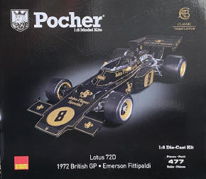
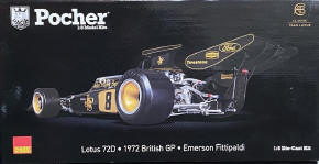
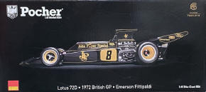
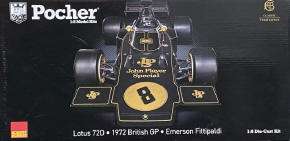
Ultimate guide for the Pocher Lotus 72D/7 from 1972 1/8 scale |
|||||||||||||||||||||||||||||||||||||||||||||||||||||||||||||||||||||||||||||||||||||||
|
by Lars Wahlström © Modeler Site |
|||||||||||||||||||||||||||||||||||||||||||||||||||||||||||||||||||||||||||||||||||||||
|
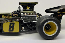
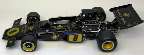
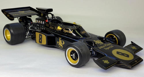
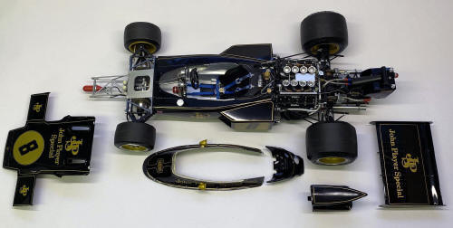
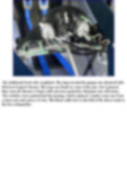
Legal Notice No material from Modeler Site any may be copied, reproduced, republished, uploaded, posted, transmitted, or distributed in any way, except that you may download one copy of the materials on any single computer for your personal, non-commercial home use only, provided you keep intact all copyright and other proprietary notices. Modification of the materials or use of the materials for any other purpose is a violation of copyright and other proprietary rights. Read More here > Legal notice The Lotus 72D has been released as a model kit many times by different manufacturers and in several scales. In 1/8 scale by Grip/Entex already in 1975. A new edition came in 1983, launched by Revell. In 2021, Pocher announced that they would release a new kit of the Lotus 72 D/7, driven by Emerson Fittipaldi in the 1972 English Grand Prix at Brands Hatch, where he also won the race.
I had already started my own research and looked for reference images and information. I also joined a Facebook group and got a lot of tips. The kit was released in the UK before in the EU, so many had already started their builds and discovered inaccuracies. The objective of this tutorial is to share with the reader the work done, not only to assemble the kit, but also to get the most out of it, adding details and missing parts, painting where necessary, etc., always guided by the references. to which I had access. Hoping it is useful to others.
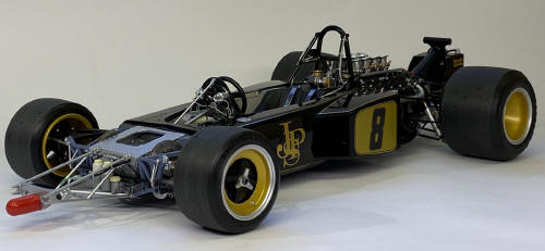
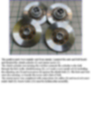
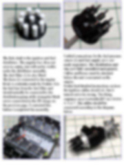
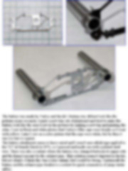
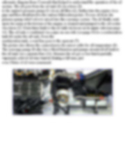
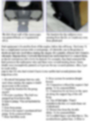
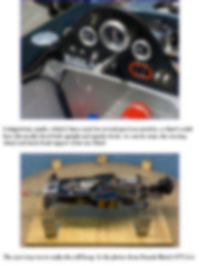
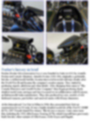
To me, judging by the assembly method, it looked like Chinese PCT made most of the 1:8 kits on behalf of various distribution brands, but I soon noticed that the Lotus 72D/7 kit was different and is likely made by another manufacturer. The quality seemed high, well on par with what I was used to from PCT. Most of the parts on the engine were cast in Zamak, which is a zinc alloy.
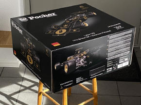
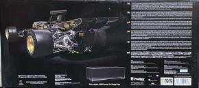
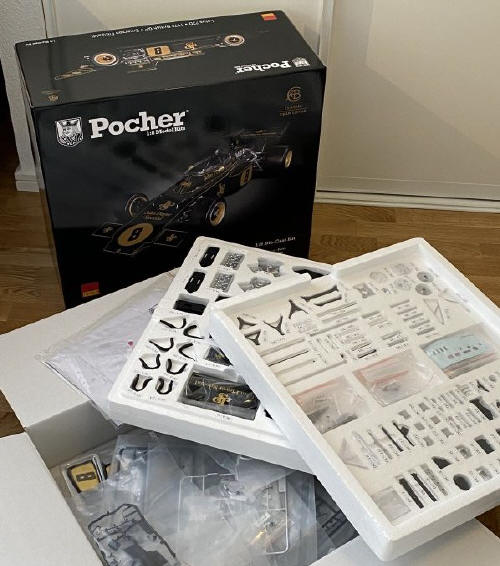
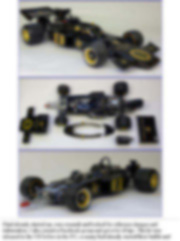
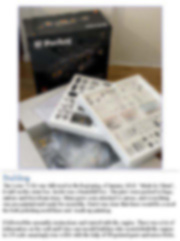
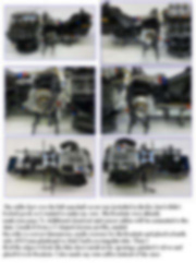
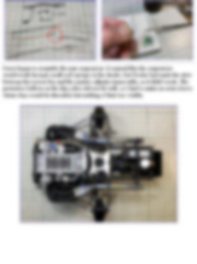
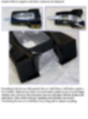
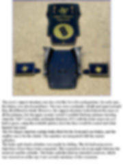
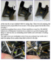
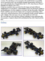
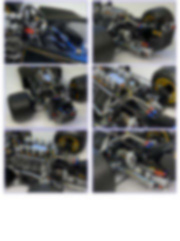
Building The Lotus 72 kit was delivered at the beginning of January 2023. "Made in China", it said on the outer box. Inside was a beautiful box. The parts were packed in bags, cartons and Styrofoam trays. Many parts were attached to sprues, and everything was pre-painted and ready for assembly. But it was clear that there would be a need for both polishing mold lines and touch-up painting.
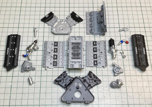
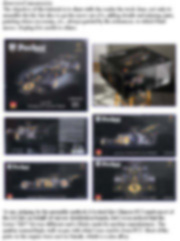
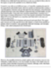
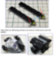
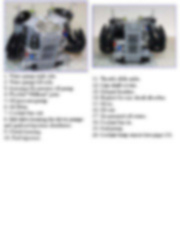
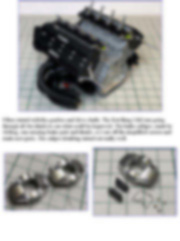
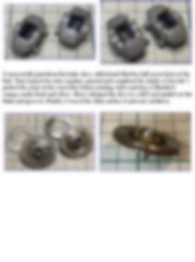
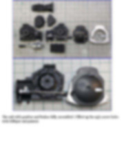
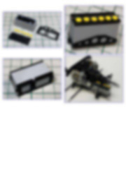
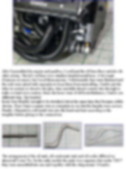
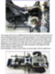
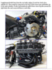
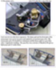
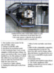
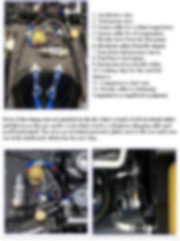
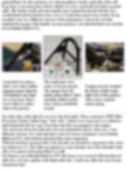
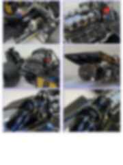
I followed the assembly instructions and started with the engine. There was a lot of information on the web and I also saw model builders who scratch-built the engine in 1/8 scale amazingly true to life with the help of 3D printed parts and micro bolts. It bothered me a little that Pocher had chosen to only use one kind of silver color for the engine, except for the camshaft covers, which were black.
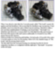
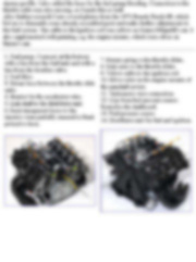
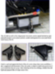
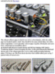
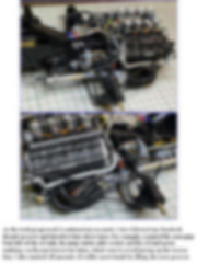
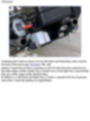
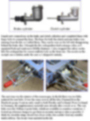
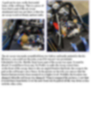
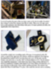
I wanted to vary with several different tones, so I started by repainting the parts for the engine block and cylinder heads, which are actually an aluminum alloy casting. I went through lots of pictures and saw that apart from the main parts of the block and cylinder head, there were many different components that were individually cast and then bolted together. Some parts were sometimes painted black, sometimes not. I kept trying to compare with pictures of surviving originals and pictures from Brands Hatch 1972. It was still hard to see everywhere and I later had to redo some as I made new discoveries. I brushed with Humbrol 56 Aluminum and sprayed semi-matte black. The engine parts were not cast in the same division as the original, so I had to look carefully at pictures of how it would be. I also painted the water and oil pumps, and Aeroquip fittings. I also added and painted a lot of bolt heads.
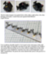
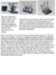
However, the assembly instructions, despite updates and corrections, were not very informative. Really bad ones, even. For example, the names of the details were not specified. I had to find that out myself in my research. Although, on the other hand, the search for facts gave me extra knowledge. This tutorial is offered in PDF format to be read or printed using Acrobat reader, contact our webmaster > Here Includes more than 200 pics, here we show only the text pages.
Esta Nota es ofrecida en formato PDF, el cual puede ser leído o impreso usando el Acrobat reader, contacte a nuestro webmaster > Aquí Incluye más de 200 imágenes, aquí solo mostramos las paginas de texto.
Big size photos are only available in our PDF format. Support us ordering our notes in PDF > Here |
|||||||||||||||||||||||||||||||||||||||||||||||||||||||||||||||||||||||||||||||||||||||