|
|
||||||||||||||||||||||||||||||||||||||||||||||||||||||||||||||||||||||||||||||||||||||||||||||||||||||||||
|
Airplanes |
|
|||||||||||||||||||||||||||||||||||||||||||||||||||||||||||||||||||||||||||||||||||||||||||||||||||||||||
|
Building a vacuform model 1/48 Toms Modelworks Sopwith 1 ½ Strutter |
||||||||||||||||||||||||||||||||||||||||||||||||||||||||||||||||||||||||||||||||||||||||||||||||||||||||||
|
by Claudio Kalicinski © 2007 Modeler Site |
||||||||||||||||||||||||||||||||||||||||||||||||||||||||||||||||||||||||||||||||||||||||||||||||||||||||||
|
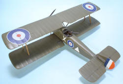
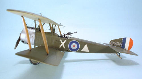
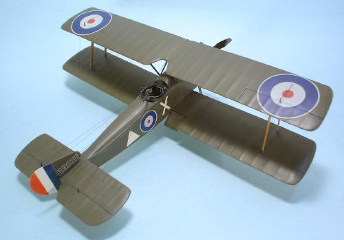
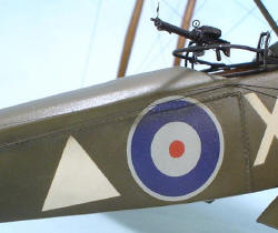
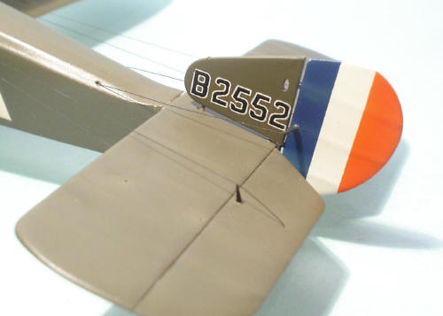
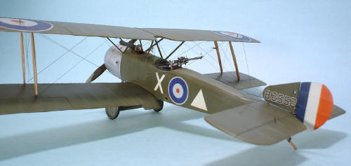
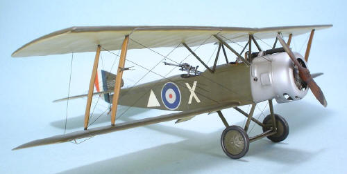
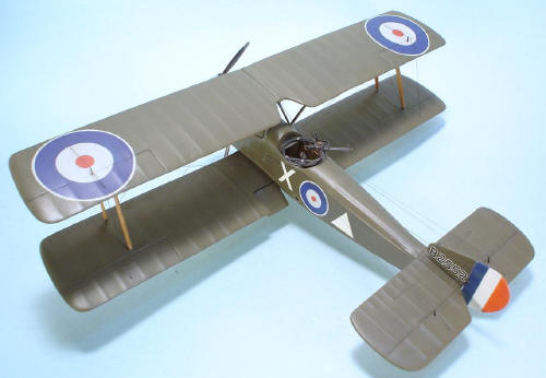
Legal Notice No material from Modeler Site any Web site owned, operated, licensed, or controlled by Damian Covalski may be copied, reproduced, republished, uploaded, posted, transmitted, or distributed in any way, except that you may download one copy of the materials on any single computer for your personal, non-commercial home use only, provided you keep intact all copyright and other proprietary notices. Modification of the materials or use of the materials for any other purpose is a violation of Damian Covalski's copyright and other proprietary rights. Read More here > Legal notice The model represents a Sopwith Strutter built by Ruston, Proctor & Co. Ltd in 1917 and delivered to the RFC (Royal Flying Corps) on August 7th 1917. With a Clerget 9z 110hp powerplant was sent with the 43 Squadron to the Lozinghem aerodrome at Flanders, Belgium, for reconnaissance missions and ground attack (as the tactical marking, the triangle, indicates). After seeing service in Belgium, it returned to England on September 29th 1918.
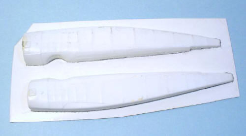
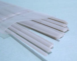
My goal when writing this article, is sharing with you my experiences in building a vacuform model and encouraging others to give one a try. Though many of us (modelers) have one or two vacuform among our kits to build, most seem to be reluctant to build those kits, in spite of the fact that they’re really good, comprising metal, etched and resin parts plus a good decal sheet. Before starting any construction, I use to gather all the available information about the model I’m going to build. This is necessary for the vacumforms too, besides of a couple of scale drawings which will be a must due to the nature of this work, since it’ll be necessary to scratchbuild a great number of parts, so, these drawings will be useful at the time of checking the symmetry and position of those parts. As main reference, I recommend two books of Albatros Publications editorial: Windsock Datafile #34, which contains information about the Strutters two- seat fighter variants and the Windsock #80 about single-seat fighters. As I built a two seat fighter version, my main reference source was the first one. The kit This Tom’s Modelworks vacuform kit comprises the fuselage, wings, rudder, landing gear legs and a few metal parts: cowling, engine, landing gear, propeller, seat, guns and gun mounting, but I only used some parts of the landing gear. As for the size and shape, it matches quite well to the plans of the Datafile 28, though it needed several corrections, mainly, in the wing chord. Another weak point of this kit, is that doesn’t supply decals and nearly no assembly instructions. As it is such a basic kit, I tried to get all the parts available around the market which saved me a lot of time. These parts were the engine, a Clerget from Copper State, the forward firing Vickers from the same brand, the Eduard PE seatbelts and the gunner’s .303 Lewis gun from Fotocut. Anyway, I had to scratchbuild a great number of parts such as: the propeller, the tail skid, the fuel pump’s wind generator, the fuselage and wing struts, the control panel together with all the interior and cowling. Assembly Preparing the parts The biggest difference between vacform modeling and building a conventional injection-moulded kit is the preparation of parts. The modeler is left with the task of cutting the parts off the sheet plastic and cleaning them up for assembly.
But, don’t be afraid, it’s not so complicated, just be careful and follow this set sequence: First, with the help of scissors, cut the parts leaving 3 or 4 mm excess plastic around each part.
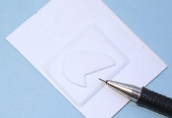
Then, take your fine marker or pencil and draw around the outline of all the parts.
Next, chose an even surface (in my case, the glass of my desk) to adhere fine grit sandpaper with adhesive tape.
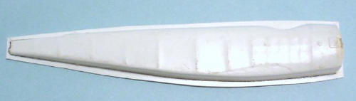
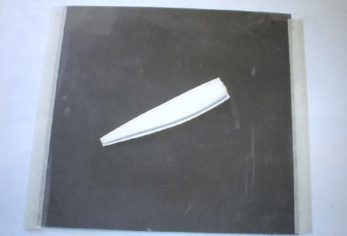
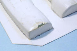
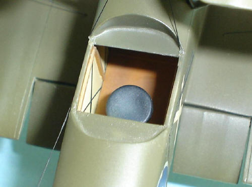
You will be left with a part that has a line around its edges (that you marked earlier), This line indicates the limit of sanding. Don’t sand above this line. Once this procedure has been followed with each plastic part, the kit can be assembled like and injection one. Fuselage As you can appreciate in the pictures, the fuselage has several problems, the most important is the plastic thinness which caused that some parts showed punctures under the minimum pressure.
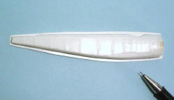
I decided to cyano glue 0,3mm plasticard to the interior in order to add more resistance.
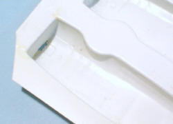
After reinforcing the fuselage, I went on detailing the interior. The interior wood frame was simulated with thin plasticard strips of different thickness.
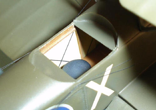
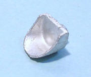
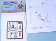
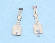
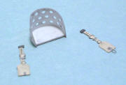
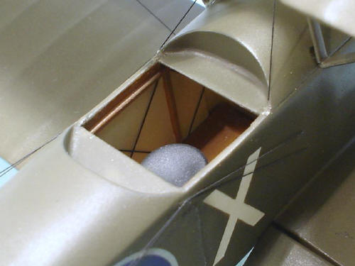
The seat supplied with the kit was replaced with a new one I scratchbuilt from platicard to which Eduard PE seatbelts(48303) were added.
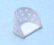
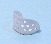
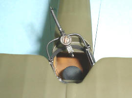
There was not a conventional seat for the gunner, just a folding stool that allowed an easier operation of his machine gun. I made it from scratch with 2,5 mm plasticard.
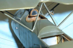
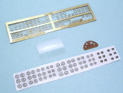
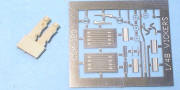
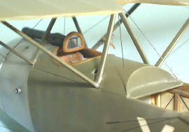
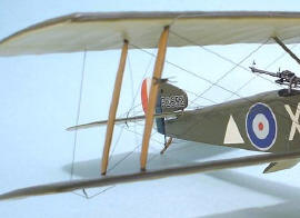
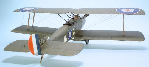
The gunner’ position didn’t include a lot more, but to match the real thing, I added several details to the cockpit such as the control column, throttle and the instruments panel which was made out of plasticard and acetate. I used the PE set from Reheat for the instruments, and the instrument faces were printed in Experts Choice decal paper. These faces are, indeed, pictures of the original instruments which were reduced and redrawn with the help of Corel Draw.
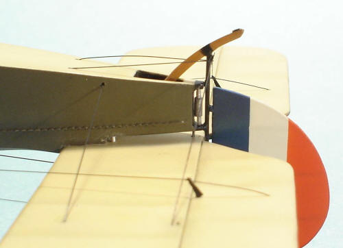
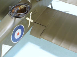
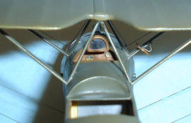
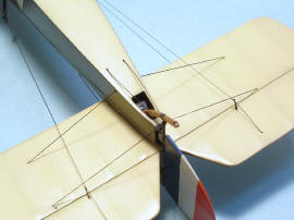
Once the interior was detailed and the exterior problems were solved, the fuselage was closed. Then, I had to rebuild the upper fuselage, not only the fabric covering but also the wood section (this only could be accomplished with the fuselage joined). I redrew the first one to give later its typical shape with the help of a watchmaker’s file and sand while the wood was simulated covering the existent frame with very thin sheets of plasticard, getting with that method the “step” effect between fabric covering and the wood, visible in the reference pictures.
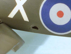
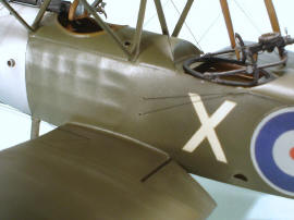
Then, I made the fuel and oil filler holes. Next, I placed the footstep on the fuselage side using the etched part from the Fotocut set.
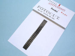
I also used another PE set from the same brand to represent the “stitching” on the right fuselage side.
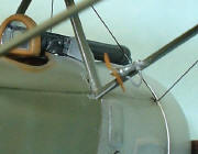
The following step was to build the tail plane incidence mechanism using hypodermic needles and stretched sprue.
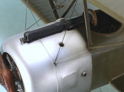
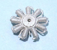
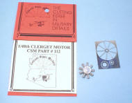
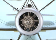
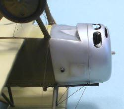
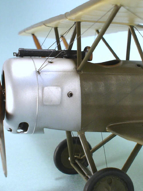
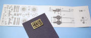
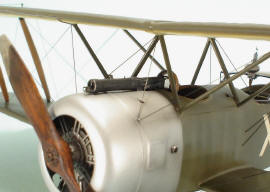
Engine, cowling and propeller As I said before, I replaced the engine with the one from Copper State which was not troublesome, it was just built, painted, and then glued to the fuselage
The difficult task was with the cowling, since it had to be vacuformed (with the help of a home-made vacu- form machine) to be replaced with the coarse metal one provided with the kit (apart from the fact that the engine didn’t fit inside the cowling ).
I made the vent holes to the vacuformed cowling and added a section located on the lower section made from a spare metal section.
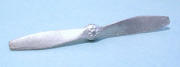
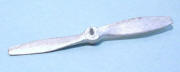
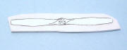
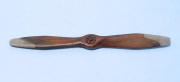
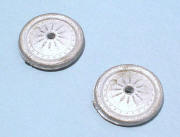
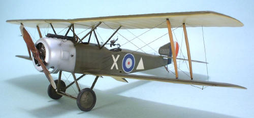
As for the propeller, it didn’t match the real thing at all, I decided to “carve” it myself. I used the Windstock Datafile 34 scale drawings as guide; cut the propeller front view and glued it to a piece of 0,4mm plasticard, then was cut around and sanded the blades to shape. It was easier than the expected. The propeller was painted wood color with grey medium blade tips. In the real thing, these parts were bronze protections painted grey. Finally, I used etched hub for the propeller.
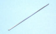
The carburettor air intakes were represented with two sections of hypodermic needle of 1,5 mm diameter placed at both sides of the fuselage.
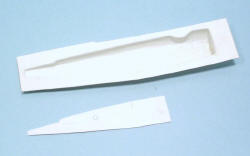
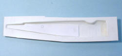
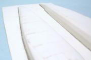
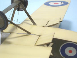
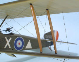
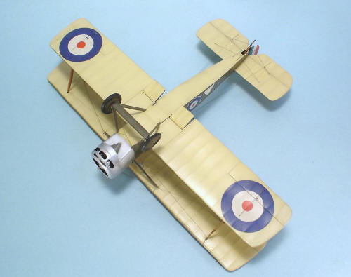
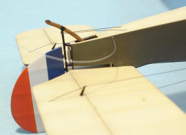
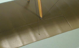
Wings and struts The wings have a good fabric covering however the wing cord is too short, so, I had to add a 1,5 mm strip to the trailing edge. I also built and added the flaps which were placed on the lower wing root and in drooped position
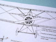
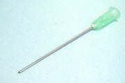
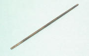
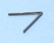
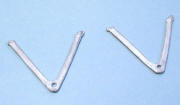
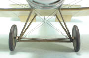
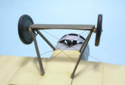
I’m very sorry for not doing the same with the tail elevator, since it started to bend downwards. As you can imagine, the wings with the steel rods inside are quite heavy, this meant a new problem. How to hold the upper wing? After trying several methods, I decided to build the fuselage struts with flattened hypodermic needles to solve this problem. I’ll explain you the way to do that: Hypodermic needles, as you know, comes in different lengths and diameters, so they can adapt to different sizes of struts. First you take an hypodermic needle of the proper size, the most important is to consider the diameter since it will determine the size of the strut. You should always use longer needles so as to have more material to work with. Then, you’ll have to heat the needle close to its plastic support, which will be removed, leaving only the steel tube. This tube will be heated up to getting it red-hot and then, cooled with cold water, this procedure will have to be repeated a couple of times. Our aim is to get a softened needle otherwise it would break. Then, it is flattened by giving slight taps (with the help of a hammer and a small anvil), and being careful not to leave marks on the steel. Once this needle is flattened, it bends and cut easily to give the “W” shape of the Strutter fuselage struts. Then, I applied red putty for cars and were sanded to get an “aerodynamic” shape
The wing struts were built using the Aeroclub set of plastic struts with aerodynamic shape (CON001). I could make them from plastic, since the weight of the wing was supported by the fuselage struts built with the needles.
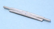
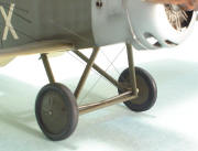
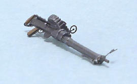
Landing gear The landing gear was perhaps the only part of the model in which I used nearly all the metal parts provided with the kit. Nevertheless, I replaced the axle with one scratchbuilt from plasticard and a hypodermic needle, then, with the help of a file, I made a partial cut in the middle, to represent the articulated axle. Besides, I had to sand the landing gear legs to give a thinner and aerodynamic shape.
Guns
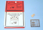
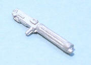
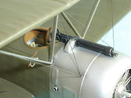
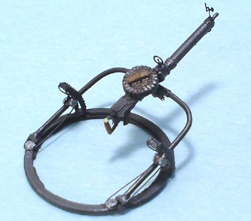
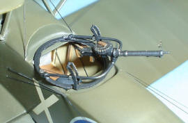
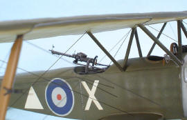
The Vickers offered nearly no problems, though I added several parts such as the ammunition feeder and windshield to get it more detailed. This last one has a quilted protection covered with leather to prevent the pilot from hurting in case of hitting against it. The windshield was scratchbuilt from plasticard and acetate.
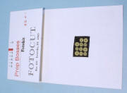
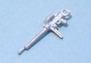
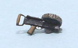
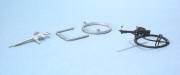
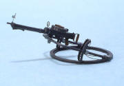
As for the Lewis, the Fotocut set is a kit in itself comprising 17 parts; the problem is that this set only supplies the mechanism box and sights while the barrel, cooling jacket, etc had to be built.
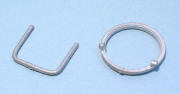
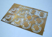
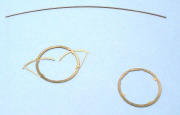
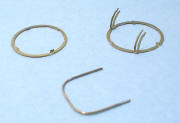
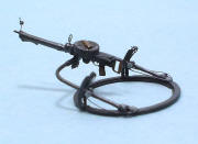
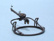
The “Scarff” ring mount was also detailed. I replaced the “U” support supplied by Aeroclub with one I scratchbuilt from 0,3m bronze wire to which I added the pulleys and bungee cord.
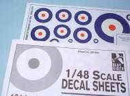
Paint and markings As the kit doesn’t provide decals, you’ll have to manage to accomplish the version you choose. Luckily, some companies such as Blue Raider or Pegasus supply the basics to achieve any version, at least regarding the British aircraft. The deciding factors at the time of choosing my version, were finally the decals I had to hand, and the available reference pictures of this airplane. The WWI aircraft have particular features as the rear view mirrors, type of gun mounts, eolic generators, etc. These features are exclusive to each aircraft, and it’s difficult to find two equal ones, so, it’s always advisable to build a subject from which you can have references pictures that help you get a faithful replica of the real thing.
I chose to represent a fighter of the 43 Squadron Royal Flying Corps with the standard camouflage scheme, this means painted with the colors used on the West front: PC10 (Pigmented cellulose 10) and varnished linen that gave a yellowish tone.
The model was painted with Model Master enamels paints. For the PC10, I used ANA 613 Olive Drab while for the linen color ANA 616 Sand. But before applying the camouflage colors; I painted white, the fuselage sides where I would paint later the tactical markings and patrol identifications which were handpainted using also handmade templates. For the metal parts, I used Model Master Aluminum Plate (buffing).
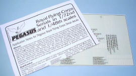
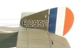
For the serial, I used the WWI serials from Pegasus. I had to put number by number, applying first the white ones and then, over them, the black ones so as to leave visible the white edge typical of the British aircraft from that period.
Simulating the wooden parts To simulate real wood is one of the biggest challenges the modeler has to face when building WWI models. It’s very difficult to get not only the proper color but also the streaks. I tried several methods until getting good results. Let’s see first of all, you should be sure about the kind of wood you like to simulate, thus you will have to investigate the specific type of wood the part you are going to paint, was built in; usually, European manufacturers used walnut, mahogany and to a lesser extent, oak. Once the type of wood was decided, you have to choose the propertint, which can be purchased at any hardware store. In my case, I tried to represent walnut. I proceeded to paint the parts in a light sand color, used Model Master ANA616 Sand that will also act as base. Then, applied a couple of layers of acrylic varnish which will act as base protection. Note, that it’s very important to let the parts drying for at least 3 or 4 days. Next, the tint was drybrushed with a hard bristle brush trying to simulate the “streaks”. It’s not so easy, the more you practice, the better your results will be. This technique was used for the propeller, wing struts and tail skid.
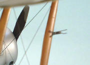
Final touches I left to place at the end of the work all those fragile parts such as the wing, elevator and rudder control horns; guns (Vickers and Lewis on its Scarff mount); the Fotocut pitot tube with its wire, the first one was placed on the strut of the left wing and the second, on the upper wing leading edge, propeller and tail skid. Finally, the fuel pump’s wind generator generator made entirely from scratch was glued on the fuselage struts.
Then, I started with the rigging, previously I had made de 0,3 mm holes on the wings, stabilizers and fuselage to install each of the wires(Foto.092;093 For the rigs, and due to the weighty upper wing, I had to use 0,1 mm plastic thread to give strength to the whole.
Conclusion This kit was a little complicated but not impossible to accomplish. It took me about 4 months work to finish, but this was not the worst… a couple of months later once I had it finished, Roden from Ukraine, released several 1/48 Sopwith Strutter excellent kits not only single but also two seat versions. Obviously, my Tom’s kit became obsolete. However, I don’t regret building it, meant a good exercise since I had never tackled this kind of kits. Hope you’ve liked it!!
Little of history Designed by the famous Sopwith Aviation Company (headed by Sir Thomas Sopwith) originally for service with the RNAS (Royal Naval Air Service), the Sopwith 1 1/2 Strutter was so nicknamed because each of the upper wings were connected to the fuselage by a pair of short (half) struts and a pair of longer struts. It was the first British fighter with a synchronized forward firing Vickers machine. The prototype two-seater flew in December 1915 and production deliveries started to reach the RNAS in February 1916. The War Office had ordered the type for the RFC at the same time, but because Sopwiths were contracted to the Navy for their entire production, the RFC orders had to be placed with Ruston Proctor and Vickers, and production from these manufacturers did not get into its stride until August. Since the Somme offensive was planned for the end of June, and the type was far more urgently required by the RFC than by the RNAS the situation was clearly farcical, and in the event some aircraft had to be transferred from one service to the other - allowing No. 70 squadron to reach the front by early July 1916, with Sopwith-built strutters originally intended for the navy. At first No. 70 did very well with their new mounts. The period of German ascendancy known as the Fokker scourge was long over, and the 1½ Strutter's long range, coupled with its excellent armament for the period - enabled effective offensive patrolling well into German held territory. Unfortunately, by the time No. 45 Squadron reached the front in October the new Albatros fighters were appearing in the Jagdstaffeln. By January 1917, when No 43 Squadron, arrived in France the type was totally outclassed as a fighter, although it was still a useful long-range reconnaissance aircraft. Like most early Sopwith types, the 1½ Strutter was very lightly built, and its structure did not stand up very well to arduous war service. It was also far too stable to make a good dogfighter. The last front line 1½ Strutters in the RFC were replaced by Camels in late October 1917. Around 1,500 1½ Strutters were built for the Royal Flying Corps and the Royal Naval Air Service, and between 4,200 and 4,500 were built in France. The Strutter enjoyed a long career and production not only in England but in France where over 4500 of different variants were manufactured against the 1300 in Great Britain. The last French Sopwiths were not replaced by later types until early 1918. Apart from these two countries, there were other users of the 1 1/2 Strutters such as USA, Russia, Japan, Latvia, Belgium and Romania But perhaps the most important thing about this aircraft, is the high technological advances in the design at the same time of being the father of a long and successful fighter series of the Sopwith such as the Triplane, the Pup and the Camel. Bibliography
Big size photos are only available in our PDF format. Support us ordering our notes in PDF > Here |
||||||||||||||||||||||||||||||||||||||||||||||||||||||||||||||||||||||||||||||||||||||||||||||||||||||||||