|
|
||||||||||||||||||||
|
Cars |
|
|||||||||||||||||||
|
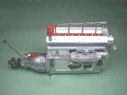
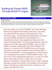
Building the Pocher KM76 1/8 scale Bugatti engine |
||||||||||||||||||||
|
by Paul Koo © Modeler Site |
||||||||||||||||||||
|
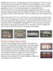
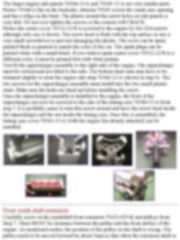
Legal Notice No material from Modeler Site any Web site owned, operated, licensed, or controlled by Mario Covalski & Associated may be copied, reproduced, republished, uploaded, posted, transmitted, or distributed in any way, except that you may download one copy of the materials on any single computer for your personal, non-commercial home use only, provided you keep intact all copyright and other proprietary notices. Modification of the materials or use of the materials for any other purpose is a violation of Mario Covalski & Associated's copyright and other proprietary rights. Read More here > Legal notice Since the release of my first CD-ROM, The Pocher Mercedes Step-by-step supplemental building instruction, I have been very pleased with the popularity and appreciation it has received on Ebay. The response has prompted me to produce a second CD-ROM, building the Pocher Bugatti 50T, a comprehensive step-by-step supplemental instruction with extensive building photos. The article presented here is just the engine section of this upcoming CD-ROM. I hope it will be helpful to modeler building the Pocher KM76 Bugatti 50T engine kit. As with the first CD-ROM, this one will mainly concentrate on the proper assembly of the model and NOT so much on customization. As many people know, Pocher kits are very complicated and consists of THOUSANDS of parts. The main focus of the supplemental instruction is to point out all the places where parts are likely to break, show the correct sequence of assembly to prevent dead corners, clarify confusing drawings, and alert the modeler to the mistakes in the assembly manual. All directions mentioned will be in reference to the engine (left/right/front /rear). Note on screws VERY IMPORTANT!!! The screws provided in the kit are made of a very soft metal that will BREAK easily. Do not force the screws into the holes. Always turn the screw slowly. To get a feel on how much force it takes to break a screw, I would suggest taking a screw (there are extras in the kit) and put it in a vise, turn the screw with a screwdriver until the screw breaks. If this is your first Pocher kit, it is very important that you practice this so you know how much force it takes to break a screw. Also, the deeper the screw hole, the higher the risk of breaking the screw. A broken screw stuck inside the hole is a frustrating matter. Install screws by heat This method will guarantee you won't break any screws. On tight fitting holes, screw in partially about half way, and then lightly push on the screw with a small soldering iron. Once the heat transfers to the screw (only takes a few seconds), the screw will melt a thin layer of plastic and slide into the hole. This "Melting Method" is very useful and will save you the frustration of broken screws. This is NOT a permanent method of assembly. The screw can still be removed easily without any plastic sticking to it. It can also be further tightened without risk of breaking the screw. Test fitting the parts Unlike Tamiya, Pocher kits have poor parts fit. All plastic pieces must be trimmed, sanded, shaped, and puttied if necessary, for a good fit. Always check the part fit and see where the interference is and sand down that area. For most of the parts, the "holes" will be too small and the pins will be too large. Do not force the parts together or they will BREAK. The holes need to be enlarged or the pins trimmed down for a good fit. It is better to trim until the fit is loose, and then use glue, instead of forcing the parts together and breaking them. Don't let the poor parts fit discourage you. Once cleaned up and assembled right, Pocher kits build up to museum quality models. Most of the "metal to plastic" parts fit are very tight. Do not force the metal fittings into the plastic holes. Forcing the parts in will crack the plastic part. Slightly enlarge the hole in the plastic with a Dremel grinding tip. Painting For a great looking model, all plastic parts should be primed and painted. Since most parts are quite large, spray paint or airbrush should be used most of the time so there are no brush lines. Only small details should be painted with brush. The plastic on Pocher kits does not accept paint evenly. Therefore, all large parts must be primed before painting.
For each step that involves different color parts, test fit the parts first, then disassemble for painting, and then reassemble. The reason it needs to be done this way is because the plastic parts will require trimming and a lot of handling. Painting the parts in advance will cause you to trim away painted area or leave finger marks in the paint. Some group of parts that are the same color can be fitted, assembled, and painted as a single part (i.e. supercharger).
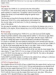
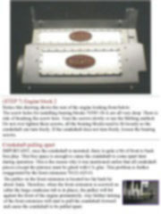
To be technically correct, the engine should be painted aluminum or silver. The Bugatti engine is not very remarkable on the outside. Various parts can be painted in different metallic shades, such as engine block, engine heads, the side covers, the front timing case, and so on. Step by step building tips Engine General note Unlike the other Pocher classic cars where the internal engine details are hidden, the Bugatti engine can be assembled as is, or it can be "built to show". The left engine head slides into place and has nothing attached to it (step 11). It can be removed easily to show the pistons and valves in action. The valve cover also snaps into place without glue. There are two panels on the engine that cover up openings (steps 6,11). These panels can be substituted with clear panels or do a "Cut-away" to show the crankcase. If you are building the engine only kit, these panels can be removed to show the internal details. Red LED's can be wired inside the crankcase to light it up. Plan in advance how much internal detail you want to show.
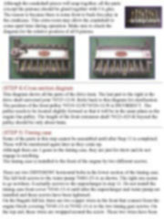
The Bugatti engine is somewhat symmetrical. Sometimes it's easy to get the front side mixed up with the rear side. Whenever possible, the direction will be stated. One way to remember is that the rear side has the molded "Y" pipe. The rear side of the large crankcase tub has the circular ridge for attaching the transmission.
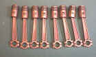
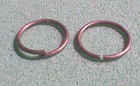
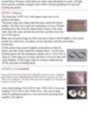
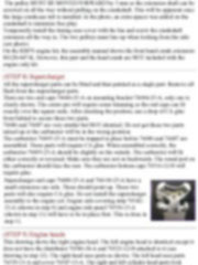
The black plastic parts are very tough. However, the gray plastic parts are very soft. With the gray plastic parts, breaking the screws is not the main concern. But instead, breaking the plastic is the main problem. Many of the holes have very thin plastic around them. Pressure on the parts can easily cause the plastic to crack. All tight holes must be carefully enlarged with a drill or Dremel grinding bit to prevent cracking the plastic. (STEP 1) Pistons
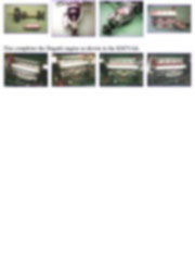
Make sure the piston rings are bent correctly so that it will fit tightly on the piston and the two ends meet. (see photo of one ring bent correctly and another incorrectly.)
This tutorial is offered in PDF format to be read or printed using Acrobat reader, contact our webmaster > Here Includes more than 40 pics, here we show only the text pages.
Esta Nota es ofrecida en formato PDF, el cual puede ser leído o impreso usando el Acrobat reader, contacte a nuestro webmaster > Aquí Incluye más de 40 imágenes, aquí solo mostramos las paginas de texto.
Support us ordering our notes in PDF > Here Apóyenos ordenando nuestras notas en PDF > Aquí |
||||||||||||||||||||