|
|
|||||||||||||||||||||||||||||||||||||||||||||||||||||||||||||||||||||||||||||||||||||||||||||||||||||||||||||||||||||||||||||||||||||||||||||||||||||||||||||||||||||||||||||||||||||||||||||||||||||||||||||||||||||||||||||||||||||||||||||||||||||||||||||||||||||||||||||||||||||||||||||||||||||||||||||||||||||||||||||||||||||||||||||||||||||||||||||
|
Techniques |
|
||||||||||||||||||||||||||||||||||||||||||||||||||||||||||||||||||||||||||||||||||||||||||||||||||||||||||||||||||||||||||||||||||||||||||||||||||||||||||||||||||||||||||||||||||||||||||||||||||||||||||||||||||||||||||||||||||||||||||||||||||||||||||||||||||||||||||||||||||||||||||||||||||||||||||||||||||||||||||||||||||||||||||||||||||||||||||||
|
Spray booth design and fan selection |
|||||||||||||||||||||||||||||||||||||||||||||||||||||||||||||||||||||||||||||||||||||||||||||||||||||||||||||||||||||||||||||||||||||||||||||||||||||||||||||||||||||||||||||||||||||||||||||||||||||||||||||||||||||||||||||||||||||||||||||||||||||||||||||||||||||||||||||||||||||||||||||||||||||||||||||||||||||||||||||||||||||||||||||||||||||||||||||
|
by Klaus Raddatz © 2003 |
|||||||||||||||||||||||||||||||||||||||||||||||||||||||||||||||||||||||||||||||||||||||||||||||||||||||||||||||||||||||||||||||||||||||||||||||||||||||||||||||||||||||||||||||||||||||||||||||||||||||||||||||||||||||||||||||||||||||||||||||||||||||||||||||||||||||||||||||||||||||||||||||||||||||||||||||||||||||||||||||||||||||||||||||||||||||||||||
|
Legal Notice No material from Modeler Site any Web site owned, operated, licensed, or controlled by Mario Covalski & Associated may be copied, reproduced, republished, uploaded, posted, transmitted, or distributed in any way, except that you may download one copy of the materials on any single computer for your personal, non-commercial home use only, provided you keep intact all copyright and other proprietary notices. Modification of the materials or use of the materials for any other purpose is a violation of Mario Covalski & Associated's copyright and other proprietary rights. Read More here > Legal notice This is not intended to be the final word on spray booth design, fan selection, or a criticism of anyone's spray booth, but to share what I know about booth design and provide a guide to take some of the experimentation out of building your own spray booth. Also, please keep in mind that we're designing a hobby paint spray booth using some of the design principles of full sized booths. This should not be interpreted as a guide to building a full sized spray booth. When it comes to fan selection, there are usually concerns about drawing too much air into the booth and contaminating your paint with dust/dirt. In determining the airflow through your booth keep in mind where your spray booth will be used, the type of spray equipment that you'll be using, and the ambient condition. While some compromises are possible, dusty environments should be addressed through means other than reduced airflow through the booth. The goal in building a spray booth is to create a healthier working environment by exhausting the paint fumes from your workshop.
Several things to consider before selecting a fan for your spray booth are spray booth size, direction of draft, airflow requirements, duct diameter and length, and static pressure. Spray booth Booth size and proportion are dependent upon need. Make sure the booth will accommodate your largest part and you can comfortably paint within those confines. If you're not sure about proportions, build a mock-up out of cardboard first and try it. Then transfer those dimensions to whatever material you're going to use to build your booth. Something to keep in mind when you're deciding on size: the larger the booth, the larger the fan you will need to exhaust it, and fan prices go up with CFM and SP ratings. Also, consider adding a plenum chamber between the fans and the filters. 1:1 spray booths use plenums to even out the airflow across the filters. Direction of draft Most 1:1 spray booths are totally enclosed and designed with either a cross-draft or a downdraft airflow. Cross-draft booths pull air across the booth from inlet filters typically located in the booth doors, into exhaust filters located directly opposite the inlet filters. Downdraft booths pull air downward from inlet filters located in the ceiling, into exhaust filters located in the floor.
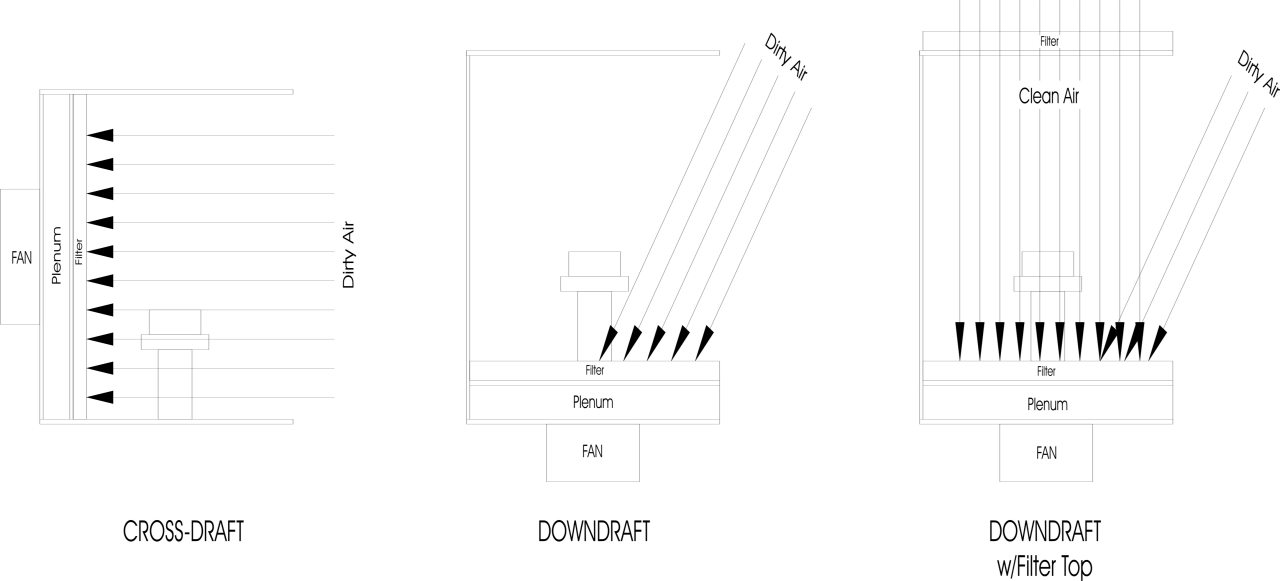
From a hobby perspective, it's not feasible to build a totally enclosed spray booth. Hobby spray booths are typically small, open-faced bench top units, drawing in unfiltered air for ventilation, as shown below. As such, problems can occur with dust and dirt settling in the paint. This is especially true in cross-draft booths where all of the air entering the booth is drawn across the part being painted. Dust contamination is reduced somewhat in downdraft booths due to the lower air volumes required for ventilation and the air being pulled downward as it enters the booth. Adding an inlet filter to the top of the downdraft booth, can further reduce the amount of unfiltered air drawn across the part.
As for venting to the top of the booth, it's normally not done that way because of the adverse affects it can have on finish quality. It's important to realize what happens when you vent to the top of the booth. First, you're working against gravity; that means you'll need higher airflow rates for proper ventilation. Secondly, the updraft pulls the atomized paint away from the part, requiring higher spraying pressures to compensate. The finish problems created by high airflow rates and high spraying pressures, are further compounded by the limited adjustments on airbrushes (versus conventional spray guns), and limited thinners and reducers available for hobby paints. Although automotive thinners and reducers have been used in hobby applications, their corrective properties may not be sufficient to overcome a poorly designed spray
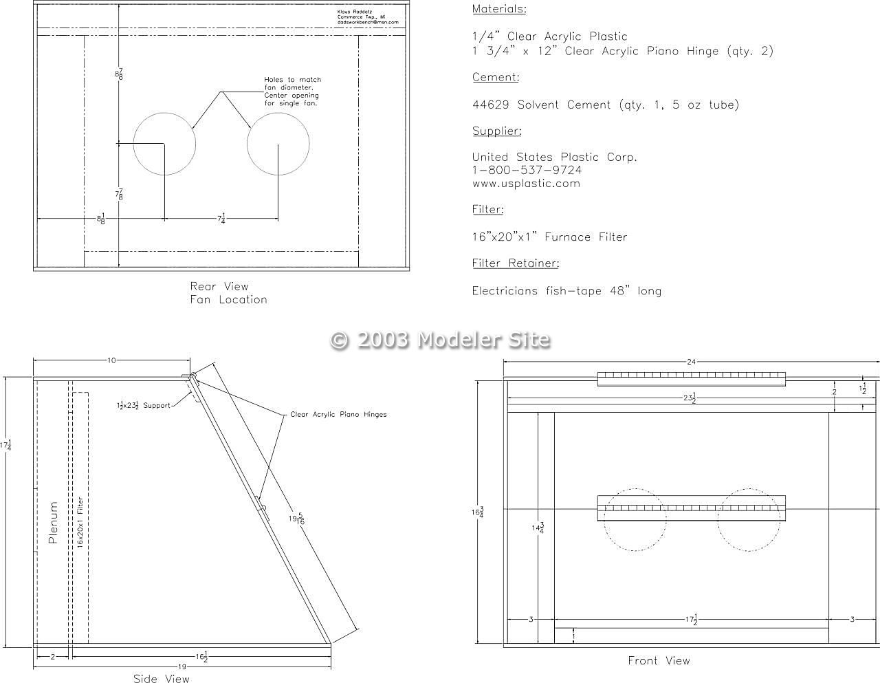
booth. Finally, when venting to the top of the booth, there is a good chance that overspray particles in the filter will fall down into the paint. It's not a good idea to hang dirt above the part you're painting. My spray booth (shown below) is a cross-draft booth that measures 17 1/4" tall, 24" wide, and 19" deep. The top of the booth is set back about 9" to provide clearance for overhead spraying, and I've added a 2" plenum chamber to even out the airflow across the filter. Another advantage of the plenum is that if I find I've installed too large of a fan, I can vent the plenum chamber to allow the fan to draw in outside air, thus reducing the airflow through the booth. I've also added a door so I can close the booth after the fans are turned off to prevent dust from settling in the paint.
Air flow requirements Once the spray booth size and direction of draft are determined, calculations for fan requirements can begin, starting with air movement through the booth. For cross draft booths, this is known as face velocity and for downdraft booths, it's known as downward velocity. Industry standards specify that the air velocity through a cross draft booth should be 100 FPM, empty, meaning no operator or parts are present. For downdraft booths the specification is 100 FPM past the operator, meaning the operator and part are present when readings are taken. Some applications require more or less velocity depending on the type and quantity of material being sprayed, the applicator being used, and the direction of draft.
The rules of thumb -- design cross draft booths with 100 FPM face velocity, and downdraft booths with 50 FPM downward velocity. A lower velocity is used for downdraft booths, first, because of gravity's effect on overspray, and secondly, when a mass (part and operator) is added to the inside of the booth, the airflow velocity increases because the internal volume of the booth has decreased. It's like pushing the same volume of air through a smaller pipe.
My booth, with a face velocity of about 75 FPM, works well with most spray cans and air brushes, although a higher airflow velocity would be better. CFM Calculations To calculate the cubic feet per minute (CFM) of air required to produce the desired face velocity in a cross draft booth or the downward velocity in a downdraft booth, use the following formulas:
Cross-draft CFM = inside height x inside width x desired face velocity (depth is not a consideration)
Downdraft CFM = inside width x inside depth x desired downward velocity (height is not a consideration)
For example, the inside height and width of my cross draft booth is approximately 18" x 24". To calculate for industry standards, multiply the height and width by 100 FPM:
1.5' x 2' x 100 FPM = 300 CFM
To meet industry standards, I need a fan capable of moving 300 CFM of air.
For my booth, I chose a reduced flow rate of 75 FPM, so I'll need a fan capable of moving 225 CFM of air: 1.5' x 2' x 75 FPM = 225 CFM.
But don't buy a fan yet, read on… Ductwork Figure out your exhaust duct routing to determine the length of the straight sections and the number of 90 and 45-degree elbows you'll use for your system. Measure the length of the straight sections, and refer to the Elbow to Straight Duct Conversion table below, to convert the elbows to straight duct, and then add it all up.
For example, my booth uses 4' of 4" straight duct, one 4" 90-degree elbow, and two 4" 45-degree elbows, as shown below. The elbow to straight duct conversion for a 4" 90-degree elbow is 6', and a 4" 45-degree elbow is 3'. Add up the duct lengths, 4' + 6' + 3' + 3' = 16', and I find my booth uses the equivalent of 16' of straight duct.
Static pressure Next, determine the static pressure in the ductwork. Static pressure (SP) is the resistance to air movement in the ducts, and is important in choosing a fan. The fan you choose must be able to deliver the required CFM at the static pressure level inherent to your ductwork.
Refer to the Air Velocities and Static Pressure table below. The values shown are for 100' of straight, smooth, aluminum duct. Find the duct diameter you'll be using and the CFM closest to the face velocity as determined above. Note the SP value and proceed to Calculate the Static Pressure in the Ductwork. Static pressure values not given were determined to be too high for practical application.
Calculate the Static Pressure in the Ductwork To calculate the static pressure of your ductwork, multiply 1/100 of your duct length by the static pressure value.
For example, to meet industry standards, I need to calculate the SP for 300 CFM airflow through 16' of 4" duct. Multiply 1/100 of the duct length (for my booth - 16' x 1/100 = 0.16) by the SP value for the duct diameter:
To meet industry standards, I need a fan capable of delivering 300 CFM @ 0.67" SP. This SP value is a little bit on the high side, so I might be better off using a 5" duct to reduce the SP and simplify fan selection.
In my booth, I use a fan capable of delivering 225 CFM @ 0.39" SP:
Also, if you're using flexible duct multiply the SP values by 3. Flexible duct is very restrictive.
I didn't include losses through the filters because it varies with filter media, however, furnace filters have minimal pressure loss when they're clean.
So, how critical is the SP to fan selection? Here's an example from a catalog, to give you some idea of how much the air volume is reduced as the static pressure increases. The free air (0.0" SP) rating of this particular fan is 320 CFM. At 0.5" SP that dropped to 50 CFM. In my booth that would produce a face velocity of about 17 FPM. Quite a bit less than the 75 FPM I'm currently using, and a pretty safe bet that my workshop will smell like paint. Not all fans will drop this much air volume, but without doing these calculations you'll never know. Also, keep in mind that many fans are rated only in free air (0.0" SP). If SP values aren't given, be careful. Contact the manufacturer to see if SP ratings are available. Some manufacturers have this information posted on their web sites. Motors/ Fans/ Lights Now, what type of fan? Bathroom, kitchen, induction motor, inside the booth, outside the booth…? You normally won't find an electric motor in the air stream of a production type spray booth, unless it's an explosion proof motor. 1:1 booths use externally mounted explosion proof motors. An explosion proof motor is certified as such by one of several industry recognized certifying agencies. None of the previously mentioned fans are explosion proof. Kitchen and bathroom fans are probably the most critical because they typically have exposed stator windings. Paint solvents, unlike cooking oils and hair sprays, can deteriorate the varnish on these windings and cause the motor to short circuit. Exercise caution if you're using these types of fans. Also, keep in mind that voltage and current levels inside a spray booth must be kept below non-sparking levels, unless the components are certified as explosion proof. Non-sparking voltage and current levels are, if I recall correctly, about 16 volts and 50 mA, way below the 120 volts and several amps that many small fans use. Ultimately, the best type of fan to use is one that keeps the motor out of the air stream.
There are booths available that use computer type axial fans. These have induction motors located in the air stream, and while they're not explosion proof, their design makes them a better choice than bathroom or kitchen fans. I've taken a few of these fans apart and found the stator windings embedded in epoxy. Since epoxy typically has a high resistance to solvents, I feel comfortable that the solvents won't migrate into the stator windings and deteriorate the insulation.
Another alternative would be a fan with an externally mounted motor, such as the Dayton shaded pole blowers, available at www.Grainger.com (see table below). These blowers have been used successfully in spray booths, but please remember, they are not explosion-proof.
To find complete specifications for these blowers, go to http://www.grainger.com and search for the blowers by stock number. Depending on the booth size and the airflow restriction of your ductwork, one of these blowers should work for you.
When it comes to lights, florescent are preferred. They run cooler, use less energy, and tend to be more color correct than incandescent lights. Lights should be mounted outside of the booth for the same reasons that apply to motors - voltage and current. Cut a hole in the booth, install a piece a plexi-glass, and mount the light over the top of that. Summing up... Last thing, if your booth is metal or plastic; make sure it has a proper electrical ground. I spent a number of years in robotic spray finishing, and I can tell you first hand that electricity, whether it's AC, DC, or static, doesn't mix well with paint, unless of course you're painting with electrostatics. But that's another story.
That's it. I hope you find this useful. If you have any questions or need more specific information, feel free to e-mail me. About me.... ....As for my interests, they lie mainly with automotive subjects; primarily sports car racing, drag racing and custom cars, but I also enjoy building aircraft from time to time. Like many adult modelers, it is difficult to find modeling time between work and family. However, modeling is a pastime I've enjoyed since my youth, and will continue to participate in as time allows now. I've met quite a few modelers via the internet who have been very helpful and a pleasure to work with. I think that is a big part of what makes this hobby so enjoyable. Klaus
|
|||||||||||||||||||||||||||||||||||||||||||||||||||||||||||||||||||||||||||||||||||||||||||||||||||||||||||||||||||||||||||||||||||||||||||||||||||||||||||||||||||||||||||||||||||||||||||||||||||||||||||||||||||||||||||||||||||||||||||||||||||||||||||||||||||||||||||||||||||||||||||||||||||||||||||||||||||||||||||||||||||||||||||||||||||||||||||||